UVM
Guide for Beginners
Sample GitHub Repo
Universal Verification Methodology is a collection of API and proven verification Guidelines written for SysVerilog
Using this, generic components can be created which is portable from one project to another
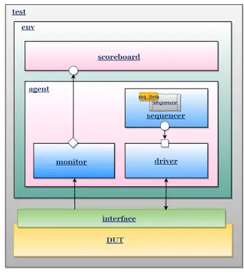
The parts of UVM
The Design-Under-Test
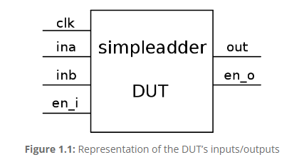
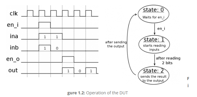
A simple ALU is taken as an example case
The Environment
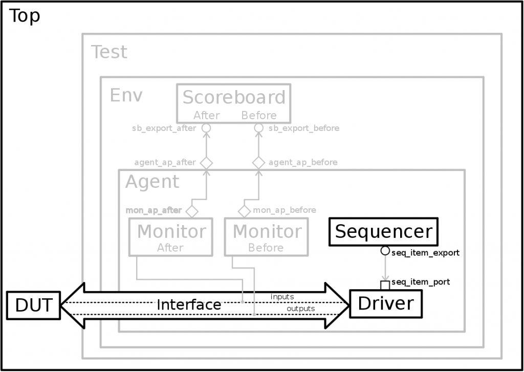
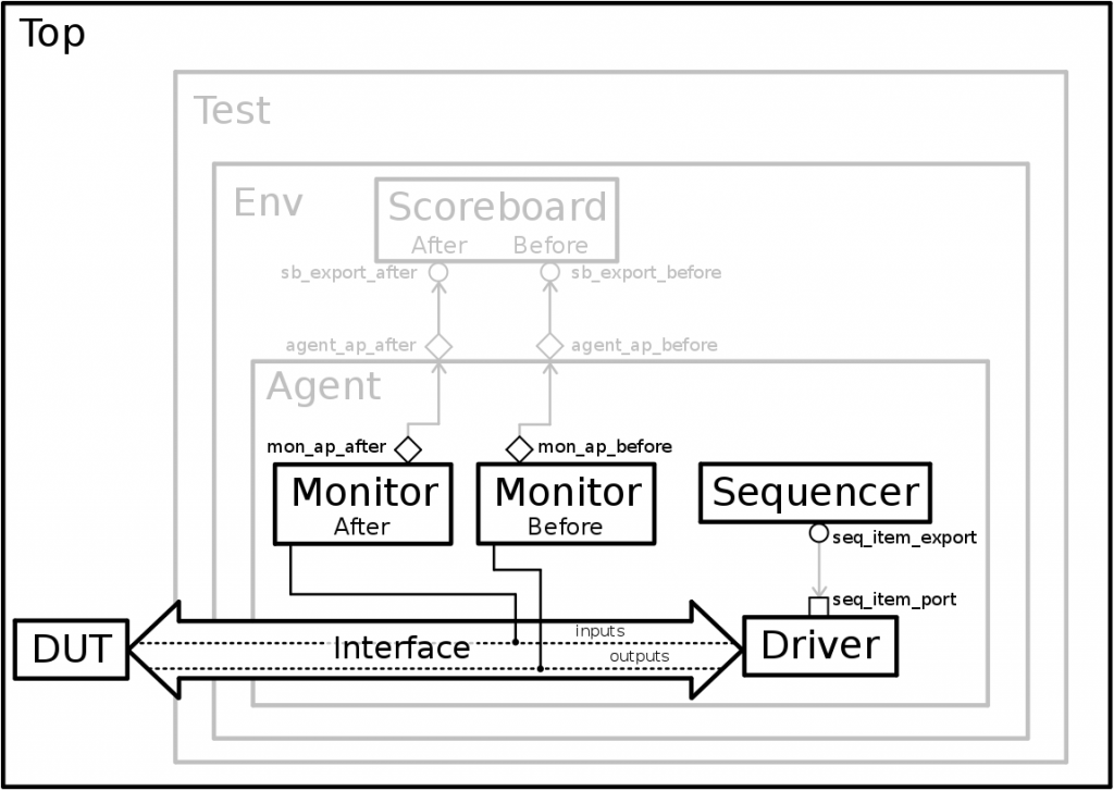
A UVM environment can be structured as follows:
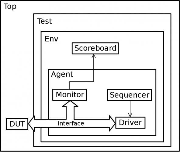
All of the above blocks are modelled as objects derived from existing classes from the UVM library, which is given below:
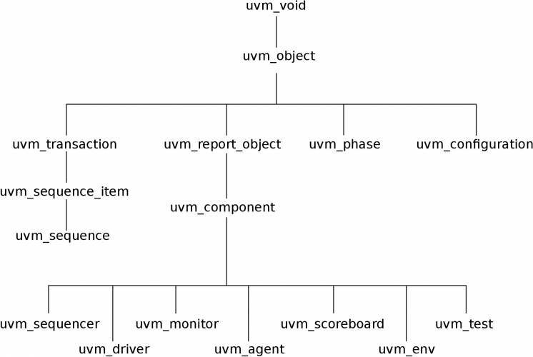
All of the above classes have simulation phases, which are ordered step of execution implemented as methods.
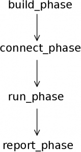
- Build Phase: Constructs components of hierarchy. eg: initialisation and construction of classes for different parts
- Connect Phase: Connects the different sub-components of a class
- Run Phase: Main phase of the execution
- Report Phase: Displays the result of simulation
The top Block
Creates instances of the DUT and the interface. Virtual interface acts as a bridge between them. The interface connects all the signals of the DUT. Virtual interface has variables which signify wires, and the monitor and driver can tap into them.
Every part of the top block has a build phase and a run phase. In the build phase, the interfaces are declared, and run phase executes the commands/code
Sequencers and Sequences
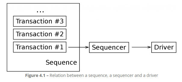
Decides what kind of data is sent to the DUT
==Transaction:== A class object, extends from uvm_transaction/uvm_sequence_item classes, that includes information needed to model communication b/w two or more components. Smallest data transfers that can be executed in a verification model. Does not depend on the communication protocols between components
Example: Object modelling communication bus of a master-slave topology. May include two variables - address of the device and the data transmitted to the said device. The transaction would be randonmising these variables to ensure all possible values are assumed to cover all possible combination
For driving a stimulus into the DUT, a driver converts transactions to pin wiggles, while a monitor performs the opposite and converts wiggles to transactions.
Monitor
Observes the communication of the DUT with the testbench. It observes the outputs, and in case of not respecting the rules, return an error
Passive component, does not drive any signals from the DUT.
A monitor covers
- The outputs of the DUT for protocol adherence
- Inputs for functional coverage analysis(What is this)
Approach:
- Sample the inputs
- Make a prediction of the output
- Compare with the result of DUT
Sends signals to the scoreboard. Functionality of observation and prediction can be decoupled and driven by two different monitors
Monitors connect transactions from the interface, and uses the analysis ports to send these transactions to the scoreboard.
TLM Ports
Transaction Level Modelling is a high-level approach to modelling communication b/w digital systems. This apporach is represented by 2 main aspects: Ports and Exports
A TLM port defines the set of methods and functions for the connection, while the export provides the implementation. They accept transaction objects as arguments
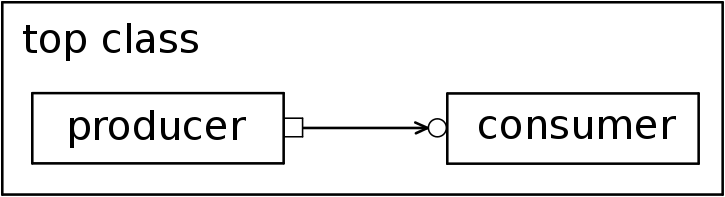
Consumer has a function that accepts transaction as an argument, producer calls that very function passing the expected transaction.
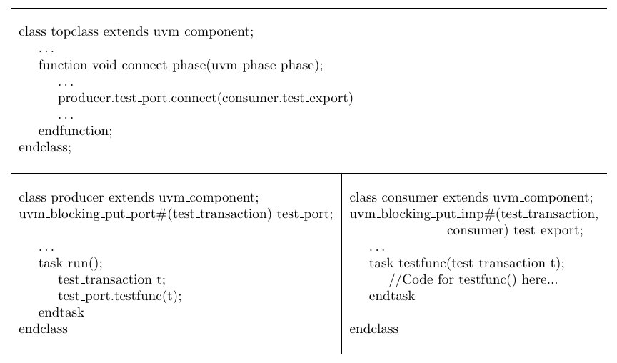
Here, the test_port in producer is connected to the test_export on the consumer, which houses the testfunc, which is then called by the producer
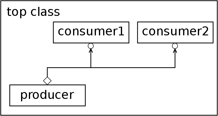
Analysis ports work like normal ports, but can also detect the number of exports connected to it, and everytime a function is asked through this, all the other components whose exports are connected to the port gets triggered

Agent
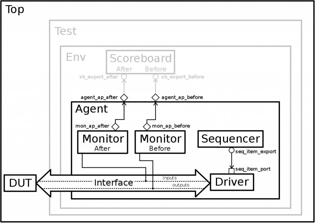
An agent does not have a run phase. It has a connect phase along with a build phase.
Monitors, Sequencers and Drivers are made during the build phase, along with the analysis ports
For the interconnects, the connect phase is utilized.
Scoreboard
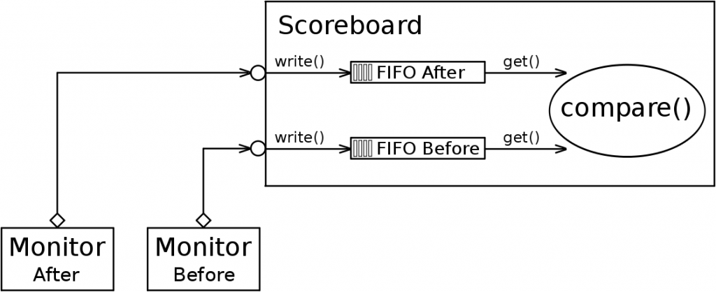
Usually the most difficult one to write, it verifies the proper operation of a design at a functional level. The prediction can also be made by the scoreboard instead of the monitor.
the compare() function is used to compare the expected and the actual outputs. To ensure the transaction streams are synchronised, the UVM FIFO is used. The exports are connected to the fifo exports, and each transaction is accessed from the FIFO via get().
Env
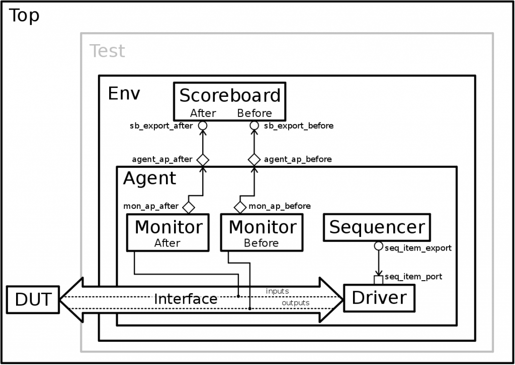
Instantiates the agent and the scoreboard, and connects them together
Test
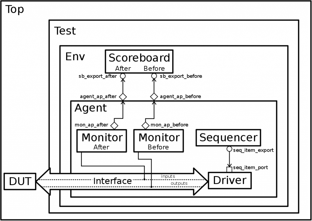
Derives from uvm_test, creates the env block and connects sequencer to the sequence
This is done so to enable the ease of modifying the sequences
Simulation
Testbench genrated random inputs and sends it to the DUT. Monitors capture data and makes predictions. Scoreboard will evaluate the functionality by matching the DUT's response
Questions
- What all transactions are written by the monitor onto the FIFO and sent to the scoreboard to compare i.e. what is the output of mon_ap_after and mon_ap_before : Every value at posedge of the clock is sent to the scoreboard
- Why should there be sync? How can the monitors be out of sync?
Notes
Virtual Class
Used to prevent multiple instances of a given class apprearing in an inheritence heirarchy
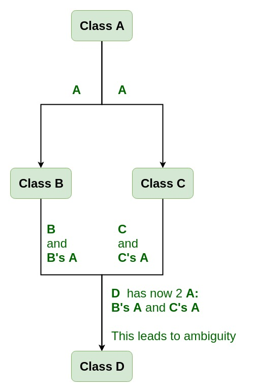
Source:GeeksForGeeks
To prevent ambiguity, A is defined as a virtual base class
class B: virtual public A
{

};
The order of virtual and public does not matter
Abstract Class
Abstract classes are specifically used as base classes. It contains atleast one pure virtual function
Virtual Functions
Static Binding: The function call is matched to the correct function during compile time (default)
#include <iostream>
using namespace std;

struct A {
	void f() { cout << "Class A" << endl; }
};

struct B: A {
	void f() { cout << "Class B" << endl; }
};

void g(A& arg) {
	arg.f();
}

int main() {
	B x;
	g(x);
}
The above example gives the following output:
Class A
Dynamic Binding: The compiler matches a function call to the definition at run time. To use dynamic binding, use virtual keyword
#include <iostream>
using namespace std;

struct A {
	virtual void f() { cout << "Class A" << endl; }
};

struct B: A {
	void f() { cout << "Class B" << endl; }
};

void g(A& arg) {
	arg.f();
}

int main() {
	B x;
	g(x);
}
The above example gives the following output:
Class B
Here, due to the virtual keyword, the compiler chooses the appropriate reference not through lvalue, but through the type of the object the lvalue refers to.
Macros in SystemVerilog
The tick symbol is used to create macros in SystemVerilog.These are very powerful, and is used to replace repetitive chunks of code with compressed ones. eg:
`define CALC(VAL1, VAL2, RESULT, EXPR) \
	RESULT = VAL1 EXPR VAL2; \
	$display("Result is %0d", RESULT);

module macro;
	int a=15, b=7;
	int c;
	initial begin
		`CALC(a,b,c,+);
		// expands to
		// c = a + b;
		// $display("Result is %0d", c);
	end
endmodule
Tasks in SystemVerilog
Generic Syntax:
// Style 1
task <task_name> (input <port_list>, inout <port_list>, output <port_list>);
 ...
endtask

// Style 2
task <task_name> ();
  input <port_list>;
  inout <port_list>;
  output <port_list>;
  ...
endtask
There are 2 types of tasks:
- Automatic Tasks
- Static Tasks
By default, tasks declared are static. If declared inside a class scope, they are automatic unless specified. The variables inside task take up the nature of tasks i.e. static and automatic
For pass by reference, use ref keyword in the declaration. const keyword can be used if the task need to change the value.
| Function | Tasks |
|---|---|
| Cannot contain simulation delay | May or may not contain delay |
| Returns a single value | Returns values according to output argument |
| Cannot call another task | May call another function or task |
https://www.edaplayground.com/x/9Yma